ISSN 1884-0760
GRACE TECHNICAL REPORTS
AO Software Behavior Model Evolution and
Synchronization: A Bidirectional Graph
Transformation Approach
Yuting CHEN Zhenjiang HU
GRACE-TR 2009–06 September 2009
CENTER FOR GLOBAL RESEARCH IN
AO Software Behavior Model Evolution and
Synchronization: A Bidirectional Graph
Transformation Approach
Yuting CHEN Zhenjiang HU
GRACE Center
National Institute of Informatics [email protected] [email protected]
September 16th, 2009
Abstract
The application of AO techniques in model driven software devel-opment still faces strong challenges. Two challenges we focus on in this report are AO model evolution and synchronization. In this re-port, we adopt a BiG (BidirectionalGraph Transformation) approach to AO model evolution and synchronization. The essential idea of our approach to AO model evolution and synchronization is that we choose UML activity diagram as the behavior model of the system, and then conduct model refactoring by extracting aspects from the activity diagrams. The potential of BiG in this work is that models evolution is effectively supported based on queries and they can be synchronized automatically. This research can provide an interesting example about the application of the bidirectional transformation to model-driven software development, which will encourage the improve-ment of BiG so that it can be really applied in practice. The research is also expected to benefit AO model-driven software development in that the AO model evolution and synchronization is possible and can be automated.
1
Introduction
tangling be prevented in AOSD because concerns are expressed separately, in a crosscutting manner, and then automatically unified into the working systems.
However, the application of AO techniques in model driven software de-velopment still faces strong challenges. Model-driven software dede-velopment is a software development methodology which introduces significant efficien-cies and rigor to the theory and practice of software development where models are the main artefacts to be developed. Two challenges we focus on in this report are AO model evolution and synchronization. Model evolu-tion refers to a gradual process in which a rough model (say source model) is transformed to a mature one (say target model), and the target model is more appropriate to be used for programming. Model synchronization refers to the process in which the modification of either the source or the target model will lead to the modification of another one, so that the consistency between the two models are maintained. The difficulty of conducting model-driven AOSD is that, although approaches to providing the developers with support in identifying and separating of concerns do exist, to the best of our knowledge, there lacks the model transformation approach to AO model evolution and synchronization. One reason is that the current models used for AOSD, such as use case diagrams [1], are not precise for describing the system’s behaviors, and therefore the model evolution and synchronization requiring precise semantics may be less efficient than expected. Further-more, the foundation of AO model evolution and synchronization is not clearly supported. For example, when a source AO model is modified, how to modify the target model may not be decided if the source model does not clearly descibe the system’s behaviors and the associated aspects.
The research is expected to benefit software development in the following aspects. Firstly, BiG provides a promising approach to model transforma-tion, which serves as the basis of the model evolution and synchronization. Therefore the research inspires the research on the AO model driven soft-ware development in that the AO model evolution and synchronization is possible and can be automated. Furthermore, the research can further ben-efit software developers in pervasively using AO techniques in practice in that AO model development, evolution, synchronization, and even aspect oriented code generation can be effectively integrated in the development. In addition, this research can provide an example about the application of the bidirectional transformation to model-driven software development, which will also encourage the improvement of BiG so that it can be really applied in practice.
This technical report is organized as follows. In section 2, we provide an overview of the application of BiG to AO model evolution and synchroniza-tion. In section 3, we introduce the graph model which is used to describe the UML activity diagram in this research. In section 4, we describe the queries on the graph model which provide developers with support in trans-forming models during model evolution and synchronization. In section 5, we describe the related work, and in section 6, we give out the conclusion and point out the future work.
2
An Overview of the BiG Approach to Model
Evolution and Synchronization
In model-driven software engineering, models serve as a means for commu-nication, documentation, and requirements capture [4]. In addition, models are the abstractions from programming languages and computational plat-forms to simplify the integration of software. We introduce in this section the models used for describing the software behaviors as well the associated AO notions. The models then serve as the basis of applying BiG to model evolution and synchronization.
2.1 Aspect-Oriented Software Behavior Models
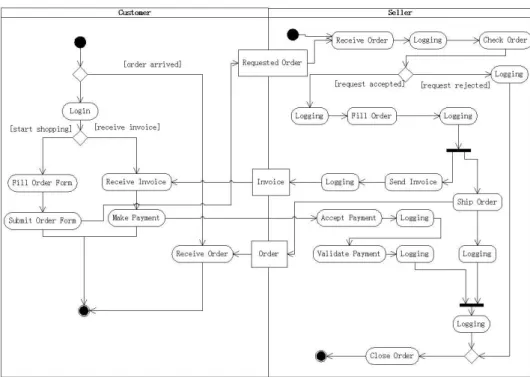
Figure 1: Online Shopping System in UML Activity Diagram
may contain activity partitions, each of which is a kind of activity group for identifying actions that have some characteristic in common [3]. Partitions divide the nodes and edges to constrain and show a view of the contained nodes. They often correspond to organizational units in a business model. They may be used to allocate characteristics or resources among the nodes of an activity.
In the research, we adopt an online shopping system as an example in order to explain the principle of the approach. As an initial step, we depict the system by using the UML activity diagram. As Figure 1 shows, the shopping activity is divided into two partitions: the customer part and the seller part. The former simulates the activities of a customer in order to commit an order, and the latter describes the behaviors of the seller when he/she receives an order form. In order to complete an order, a customer needs to at first login the system and then fill in and submit the order form. The seller needs to validate the order form when the order form is received, and then fill the order. After that, the seller needs to ship the order as well send the invoice to the customer. Once the customer receives the invoice, he/she needs to make a payment. The seller will close the order after the order is shipped and the payment is received. Note that all actions in the seller part need to be logged.
In spite of using the above mentioned activity diagram to develop the system, the programmers may also hope to seperate the crosscutting con-cerns of the system in order to prevent code tangling. For this reason, the refactoring of the model may be necessary so that aspects can be modelled. One main advantage of this is that the programmers can use the AOP tech-nique in their programming and thus the consistency between the model and the program can be maintained.
fa-cilities for modelling aspects. In our research, we would adopt the activity partition above mentioned for describing an aspect, because an activity par-tition has the similar semantics about crosscutting concerns in that different parts of a system including aspects can be crosscutly organized using activ-ity partitions. A partition can therefore contain not only the normal actions, but also crosscutting concerns (i.e., aspects), which will be explained in the next subsection.
2.2 AO Model Evolution
Aspect-Oriented Software Development focuses on the identification, specifi-cation and representation of crosscutting concerns and their modularization into separate functional units as well as their automated composition into a working system [1]. The main purpose of AO model evolution in this re-search is to extract advice components of aspects from the UML Activity Diagram (saymodel before evolution) so that the main concerns and the crosscutting concerns of the system are separated and clearly described in themodel after evolution. A graphical representation of the AO model evolution is that the developers can drag some actions and then drop them in a specific Aspect Partition.
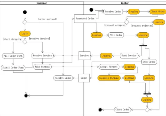
Let’s adopt the online shopping system as an example. As shown in Figure 2, the actions for logging and authentication can be modelled as the advice components of an aspect, each of which is further contained in an individual activity partition. Suppose we have a tool for providing the developers with support in AO model evolution. A developer using the tool is expected to ‘drag and drop’ actions (or the associated objects) to form an Advice Partition in the Aspect Partition. Suppose the developer wishes to choose the logging action after the condition [request rejected] to form an advice. A drag and drop of this logging action to the aspect partition will help to create an advice partition (see Figure 3), and the tool will help the developer to reorganize the activity diagram so that it holds precise semantics and comprehensible structure. Note that the extraction of actions from the activity diagram should be conducted manually, because only human beings can make correct decisions when choose the actions to be the advice.
Although we describe the AO model evolution as a ‘drag and drop’ of the actions in the model, the evolution process in this research is radically on the basis of the BiG approach. That is, we adopt bidirectional model trans-formation approach to model evolution, and the drag and drop of actions in the diagram is intepreted as queries on the diagram.
Figure 2: Identifying Advices from Online Shopping System
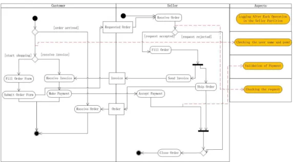
Figure 4: AO Model for Online Shopping System
in Figure 1, except that several actions are extracted to form the advice partition in the aspect partition. Note that the advice ‘Logging After Each Operation in the Seller Partition’ is used in this figure for representing all logging actions in the seller partition. Such a combination of the similar actions to be one action is also correspondent to the notion ‘Pointcut’ in AOP.
2.3 AO Model Synchronization
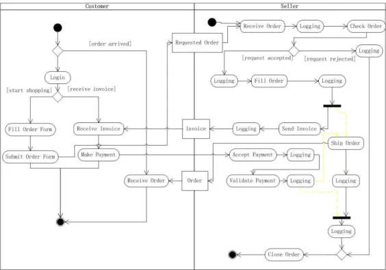
An important activity of model-driven software development is model syn-chronization. In this research, after the AO model evolution is conducted, the source and target models usually coexist and may evolve independently. One reason for this is that the designer may have to discuss with the cus-tomers and improve the design on the basis of the source model, while may go through with the programmers by using the target model so that the programmers can develop the system using AOP techniques. However, it is usually necessary to modify either the source or the target model in order to improve the comprehensibility, preciseness, or satisfiability of the model. How to propagate modifications correctly across models in different formats and guarantee system consistency remains unsolved. For example, when us-ing the online shoppus-ing system, the seller may require that the order must be shipped after the payment is validated. In order to satisfy this requirement, the designer needs to modify the activity diagram by adding the control flow between the processes ‘Validate Payment’ and ‘Ship Order’, and removing the control flow between ‘Fill Order’ and ‘Ship Order’ and that between ‘Validate Payment’ and ‘Close Order’, as Figure 5 shows. Thus a modifica-tion of the target AO model is necessary in order to satisfy this requirement and be consistent with the source model.
Figure 6: A Compositional Framework for Bidirectional Model Transforma-tion Framework
consistency. To the best of our knowledge, BiG is one of the few approaches which provide the developers with support in synchronizing the models be-fore/after evolution automatically, and any change of the source model leads to a corresponding change of the target model, or vice versa. The research issue about this is: the modification of the source model may lead to the modification of the target model in its behavioral part, aspect part, or both, how to define the transformation rules still remains unsolved. Furthermore, any modification of the target model may not only lead to the modification of the source model, but also cause the consistency violations between the aspects and the behaviors of the target model. Therefore we need to develop methods to find out and remove these consistency violations.
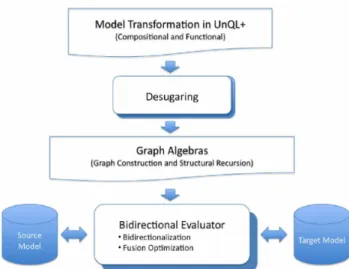
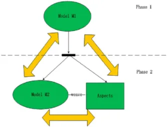
2.4 Bidirectional Model Transformation
Figure 7: Consistencies among Models
In the research, since the source model is evolved to a target model describing the system’s behaviors and the associated aspects, the graph algebra among the source model, target model, and aspect part need to be efficiently evaluated. In addition, the aspects need to be woven into the target model so that the target model provides the expected functionality of the objective system. Therefore the consistencies to be maintained not only cover that between the source and target models, but also that between the source model and the aspect model and that between the target model and the aspect model, as Figure 7 shows.
3
Graph Data Model for UML Activity Diagram
A UML diagram is usually modelled in XMI 2.1 [7, 8], which provides an EMF-based implementation of UML 2.x OMG metamodel for the Eclipse platform. For example, a UML activity diagram containing one activity partition which includes an initial node, an activity final node, and a control flow between the two nodes is written in XMI 2.1, as next shows:
—————————————
<?xml version="1.0" encoding="UTF-8"?> <uml:Model xmi:version="2.1"
xmlns:xmi="http://schema.omg.org/spec/XMI/2.1" xmlns:uml="http://www.eclipse.org/uml2/2.1.0/UML" xmi:id="_qb8akM37EdqwVrslYOdUDA"
name="Example">
<packagedElement xmi:type="uml:Activity" xmi:id="_VoiNIKDoEd6rOcWcxV8kMg" name="Example">
outgoing="_f6RiuqDoEd6rOcWcxV8kMg" inPartition="_bvF7sKDoEd6rOcWcxV8kMg"/> <node xmi:type="uml:ActivityFinalNode"
xmi:id="_fLVZEKDoEd6rOcWcxV8kMg" name="ActivityFinalNode1"
incoming="_f6RiuqDoEd6rOcWcxV8kMg" inPartition="_bvF7sKDoEd6rOcWcxV8kMg"/> <edge xmi:type="uml:ControlFlow"
xmi:id="_f6RiuqDoEd6rOcWcxV8kMg" name="ControlFlow1"
source="_eH1UsKDoEd6rOcWcxV8kMg" target="_fLVZEKDoEd6rOcWcxV8kMg"
inPartition="_bvF7sKDoEd6rOcWcxV8kMg"> <guard xmi:type="uml:LiteralBoolean"
xmi:id="_f6Riu6DoEd6rOcWcxV8kMg" value="true"/>
<weight xmi:type="uml:LiteralInteger" xmi:id="_f6RivKDoEd6rOcWcxV8kMg" value="1"/>
</edge>
<group xmi:type="uml:ActivityPartition" xmi:id="_bvF7sKDoEd6rOcWcxV8kMg" name="ActivityPartition1"
node="_eH1UsKDoEd6rOcWcxV8kMg \
_fLVZEKDoEd6rOcWcxV8kMg" edge="_f6RiuqDoEd6rOcWcxV8kMg"/>
</packagedElement> </uml:Model>
—————————————
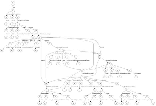
Since the BiG approach accepts only root edge-labeled graphs as inputs [5, 6], it is necessary to translate the activity diagram in XMI to the root edge-labeled graph. Next we introduce some translation rules, and a root edge labeled graph after translation of the above UML activity diagram in XMI2.1 is given in Figure 8.
• each element in the xmi file is translated to a subgraph of the root
edge-labeled graph;
• the hierarchy of the diagram is maintained in the root edge-labeled
graph. The attributes of an element A are translated to the children of A. If an element, say A, belongs to another element B, we need to add a link with the information ‘has child’ from B to A.
• if the value of an attribute is an id, add a link from the parent to the
Figure 8: An Example of A Root Edge-Labeled Graph
4
Queries
BiG adopts UnQL+, a graph querying language based on structural recur-sion, for graph query and transformation. UNQL+ has a convenient and powerful select-where structure for extracting information from a graph [5, 6]. In addition, UnQL+ provides a new replace-where construct suitable for specifying model transformation. Another two queries, delete and append, are also supported for model transformation. In this research, it is neces-sary to compose the basic query statements to complete the graphical ‘drag and drop’ for AO model evolution. Here we provides some typical query examples, including adding or deleting an element, modifying a value on an edge, and moving a subgraph.
4.1 Add/Delete An Element
The next program shows a query which is used to add an aspect partition to the activity diagram.
————————————— Query 1:
select letrec
id: {"Aspect":{}},
name: {"Aspect":{}}U $g}} | h1({$l : $g}) = {$l: h1($g)}
in h1($tempdb) where $tempdb in (
select letrec
sfun h1( {_azc1IIl2Ed6pFZkO8NYKpA : $g})
= {_azc1IIl2Ed6pFZkO8NYKpA:{haschild:{Aspect:{}} }U $g} | h1({$l : $g}) = {$l: h1($g)}
in h1($db) )
—————————————
In this example, the activity diagram has an id azc1IIl2Ed6pFZkO8NYKpA. We have added a child haschild: Aspect to the root of the activity diagram and then achieved a temp database $tempdb through defining a query on the database $db by:
—————————————
$tempdb in( select letrec
sfun h1({_azc1IIl2Ed6pFZkO8NYKpA : $g}) =
{_azc1IIl2Ed6pFZkO8NYKpA:{haschild:{Aspect:{}} }U $g} | h1({$l : $g}) = {$l: h1($g)}
in h1($db))
—————————————
where the function h1 is applied to $db. After that, we define the query on $tempdb in order to add new attributes including the type, id, and name to Aspect.
The query for deletion of an advice with id Advice 001 is given in the next part:
————————————— Query 2:
select letrec
sfun h1({Advice_001 : $g}) =
{Advice_001:{elementtype:{"group":{}}, type:{"uml:ActivityPartition":{}}, id:{"Advice_001":{}},
name:{"Advice":{}}U $g}} | h1({$l : $g}) = {$l: h1($g)} in h1($db)
4.2 Move An Element
Query 3is a query statement which supports the finding of a pointcut with id ‘Pointcut 001’. The pointcut is then moved to be a subgraph following the edge with value ‘ qb8akM37EdqwVrslYOdUDA’. In this example, the name of the pointcut is changed to ‘newname’.
————————————— Query 3:
select letrec
sfun h1({haschild: $g}) = h2($g) | h1({$l : $g}) = {$l: h1($g)}
and sfun h2({Pointcut_001 : $g}) = {} | h2({_qb8akM37EdqwVrslYOdUDA : $g}) =
{_qb8akM37EdqwVrslYOdUDA: {haschild: $child} U h1($g) } | h2({$l : $g}) = {haschild: {$l:h1($g)}}
in h1($db) where $child in( select letrec
sfun h1({haschild: $g}) = h2($g) | h1({$l : $g}) = h1($g)
and sfun h2({Pointcut_001 : $g}) = {Pointcut_001 : $g} | h2({$l : $g}) = h2($g)
in h1($db) )
—————————————
4.3 Modify A Value
Query 4 is a query statement which supports the modification of the at-tribute value of a pointcut with id ‘Pointcut 001’. In this example, the name of the pointcut is changed to ‘newname’.
————————————— Query 4:
select letrec
sfun h1({Pointcut_001 : $g}) = {Pointcut_001: h2($g)} | h1({$l : $g}) = {$l:h1($g)}
and sfun h2({name : $g}) = {name:{"newname":{}}} | h2({$l : $g}) = {$l: h2($g)}
in h1($db)
Two transformation queries that are useful but still unsolved are: (1) replacing several values on the edges of the graph. (2) add/remove an edge from a specified node to another.
4.4 Composition of Queries and Optimization
Simple queries can be composed to a complex query (seeQuery 1). Suppose two simple transformations (sayf1 andf2) should be conducted on a graph
g, andf1 and f2 do not affect each other. We can then compose f1 and f2
in that f1 receives the graph g as its input, and f2 receives the output of the transformation f1 as its input, as next formula shows. The query should be optimized because it may not be necessary to achieve a new database (i.e.,
f2(g)) in order to perform a second query.
(f1⊕f2)(g) =f1(f2(g))
However, the transformations to be composed may be tangled and the order of performing the transformations may be crucial. For example, the resulting graph of performing two transformations (deletion an element e
and adding e to the graph) can be different if the order is reversed. The approach to composition and optimization of queries is an important issue, part of which has been addressed in BiG.
5
Related Work
This section introduces some potential applications of BiG in practice.
• Model driven software development [10-13]. A promising domain that
can be strongly supported by BiG is software evolution and syn-chronization, such as the approach proposed in this report. Poten-tial applications in this domain include the development of an MVC (Model-View-Controller) structure for software system and its auto-matic maintenance [15], the transformation among UML diagrams (or other kinds of software models) and their synchronization, model refac-toring, and stepwise reverse engineering.
• Code generation [16, 17] and refactoring [14]. Code generation in
improved. BiG can support the program refactoring and the synchro-nization, in a similar manner to what we conduct on model evolution and synchronization.
• Data management [18-23]. In order to map data across paradigms, the
developers sometimes need to merge the data from multiple sources, and exchange it between sources. In addition, data needs to be syn-chronized if replicas in different formats exist. A more recent research effort allows declarative mappings to be specified between classes and XML schemas. BiG can provide with such supports in transforming, integrating, and exchanging data.
• Some other applications. A summer project in Shanghai Jiaotong
Uni-versity for sophomores is that they need to optimize a schedule through transforming the schedule to an event graph, and then calculating the longest critical path of the graph. BiG can provide the students with support in simplifying the development of the project.
6
Conclusions and Future Work
In this technical report, we describe a bidirectional model transformation approach to model evolution and synchronization. The essential idea of our approach is that we choose UML activity diagram as the behavior model of the system, and then conduct model refactoring by extracting aspects from the activity diagrams. The potential of BiG in this work is that models evo-lution is effectively supported based on queries and they can be synchronized automatically.
In the future, we would improve the approach proposed in this paper by defining more complex queries and optimizing them, and then refine the ‘drag and drop’ of the activity diagrams on the basis of the queries. We would also develop the tool to support the approach to model evolution and synchronization. An experimental comparison between BiG and other approaches (such as the Query/View/Transformation approach [9]) to AO model evolution and synchronization is necessary.
7
References
1. Robert E. Filman and Tzilla Elrad and Siobhan Clarke and Mehmet Aksit. Aspect-Oriented Software Development. Addison-Wesley. 2005.
2. http://www.biglab.org/. 2009.
3. OMG. Unified Modeling Language (UML), version 2.2.
4. David S. Frankel. Model Driven Architecture: Applying MDA to En-terprise Computing. John Wiley & Sons, ISBN 0-471-31920-1.
5. Peter Buneman, Mary F. Fernandez, Dan Suciu. UnQL: A Query Language and Algebra for Semistructured Data Based on Structural Recursion. VLDB J. 9(1): 76-110. 2000.
6. Soichiro Hidaka, Zhenjiang Hu, Hiroyuki Kato, Keisuke Nakano. A Compositional Approach to Bidirectional Model Transformation, New Ideas and Emerging Results Track of31st International Conference on Software Engineering (ICSE 2009, NIER Track), Vancouver, Canada, May 16-24, 2009.
7. OMG. MOF 2.0 / XMI Mapping Specification, v2.1.1.
http://www.omg.org/technology/documents/formal/xmi.htm. 2009
8. Eclipse. UML2. http://www.eclipse.org/uml2/. 2009.
9. OMG. Meta Object Facility (MOF) 2.0 Query/View/Transformation Specification. http://www.omg.org/spec/QVT/1.0/PDF. 2007.
10. M. Antkiewicz and K. Czarnecki. Design Space of Heterogeneous Syn-chronization. InGenerative and Transformational Techniques in Soft-ware Engineering II, International Summer School, GTTSE 2007, Re-vised Papers, volume 5235 of LNCS, pages 3–46. Springer, 2008.
11. A. Schurr. Specification of Graph Translators with Triple Graph Grammars. In International Workshop Graph-Theoretic Concepts in Computer Science, volume 903 of LNCS. Springer, 1995.
12. P. Stevens. Bidirectional Model Transformations in QVT: Semantic Issues and Open Questions. In International Conference on Model Driven Engineering Languages and Systems (MoDELS 2007), Pro-ceedings, volume 4735 of LNCS, pages 1–15. Springer, 2007.
13. Y. Xiong, D. Liu, Z. Hu, H. Zhao, M. Takeichi, and H. Mei. To-wards automatic model synchronization from model transformations. In ASE ’07: Proceedings of the twenty-second IEEE/ACM interna-tional conference on Automated software engineering, pages 164–173. ACM, 2007.
14. Fowler, Martin. Refactoring. Addison-Wesley. 1999.
16. ALTOVA. Generate Application Code from UML Models.
http://www.altova.com/umodel/uml-code-generation.html. 2009.
17. Benoit Marchal. Working XML: UML, XMI, and Code Generation. http://www.ibm.com/developerworks/xml/library/x-wxxm23/. 2004.
18. A. Fuxman, P. G. Kolaitis, R. J. Miller, and W. C. Tan. Peer data ex-change. ACM Transactions on Database Systems (TODS), 31(4):1454– 1498, 2006.
19. T. J. Green, G. Karvounarakis, Z. G. Ives, and V. Tannen. Update Ex-change with Mappings and Provenance. InProceedings of the 33rd In-ternational Conference on Very Large Data Bases, VLDB 2007, pages 675–686. ACM, 2007.
20. A. Y. Halevy, Z. G. Ives, D. Suciu, and I. Tatarinov. Schema Mediation in Peer Data Management Systems. InProceedings of the 19th Inter-national Conference on Data Engineering, ICDE 2003, pages 505–516. IEEE Computer Society, 2003.
21. G. Karvounarakis and Z. G. Ives. Bidirectional Mappings for Data and Update Exchange. In 11th International Workshop on the Web and Databases, WebDB 2008, Proceedings, 2008. Available at
http://webdb2008.como.polimi.it/images/stories/WebDB2008/paper35.pdf.
22. S. Kawanaka and H. Hosoya. biXid: a bidirectional transformation language for XML. In ICFP ’06: Proceedings of the eleventh ACM SIGPLAN international conference on Functional programming, Pro-ceedings, pages 201–214. ACM, 2006.